AGA Geodimeter Model 8
Technical Description
The Geodimeter Model 8 is designed for long distance geodetic measurements. It features several vital advantages, for example for example :
Long range, up to 60 km (40 miles) in daylight,
Short measuring time, x min per distance,
High accuracy, 6 mm +1 ppm,
Low weight, 23 kg (51 lb)
Low power consumption, 75 W 12 V DC
The abovementioned improvements are mainly the consequences of a laser being used as a light source, a new demodulation system and completely transistorised electronic circuits.
On the following pages we are mainly going to discuss the laser and the demodulation system which are the principal changes in the Model 8.
Laser as a light source
In the Model 8 the long range (as compared to earlier types of Geodimeter) is attained by using a laser as a light source; to be more exact a Helium–Neon (HeNe) gas laser. In spite of the fact that the laser output power is only about 5 mW a longer range, and under daylight conditions are better signal to noise ratio is attained than with 100 W mercury lamp. The reason for this is as follows.
The light from the mercury lamp is uniformly radiated in all directions. The cone that is formed by the first lens in the optical system facing the mercury lamp is, however, a very small part of the total radiation. The rest cannot be utilised but is instead absorbed by the housing and emitted in the form of heat. The laser emits its light beam in a pencil of rays that is about 1 mm in diameter with a very small divergence, about 1.5 metres per kilometre (i.e. at a distance of 1 km an area 1.5 m in diameter is illuminated). With the use of an optical accessory, a beam expander, this divergence can be further decreased. With regard to normal requirements for stability of the stand and signals, the smallest divergence which can be practically utilised is about 15 times less, i.e. an area with a diameter of 1 m at a distance of about 10 km. Since the power in every cross-section of the beam is the same, neglecting absorptions into the atmosphere, it is easy to understand the importance of keeping the divergence as low as possible. Due to the fact that the divergence is reduced 15 times, the illuminated area will be 225 times less and since the radiation is the same, the intensity of the light is 225 times greater. Each prism in the reflector will thus reflect 225 times more light to the receiver than if the laser beam strikes the prism without passing the beam expander.
There is another characteristic of the laser beam which can be used to improve measuring in daylight. A tungsten lamp as a radiation with its maximum value lying in the infrared section of the spectrum, and with a radiation intensity that diminishes as the wavelength become shorter. The mercury lamp, which is a luminous discharge lamp, emits its radiation at a number of wavelengths characteristic for mercury, several of which lie within the section of the spectrum (yellow-green) sensitive to the eye and photocells. However, within this section, the radiation from the sun also obtains its maximum intensity which, when measuring during daylight, limits the possibility of the Geodimeter of separating the modulated light signals from the background light, which also enters the receiver optics, thereby developing a disturbed, noisy signal in the photocells. On the other hand, the HeNe laser emits all of its radiation with a very low very narrow bandwidth in the red section of the spectrum. There the radiation from the sun is considerably less. An optical filter in front of the photocells is highly transparent for the laser beam but just the opposite for light of other wavelengths within the reign sensitive to the eye and photocells. The laser beam being reduced by about 30% but light of other colours reduced by about 10,000 times.
Due to this fact, measurements made during daylight have almost the same character as those made in darkness. Even when localising the reflector, the filter increases the contrast to such a high degree that it is easy for the eye to distinguish even a weak reflection from a distant reflector.
In this context it is perhaps appropriate to discuss the assumed danger of the laser beam. Here it appears that the gas laser used in the Geodimeter is confused with the rubidium laser which is used in certain types of distance measuring for military purposes. While the gas laser emits a continuous radiation with low power, the rubidium laser emits very high power in the order of 100 megawatts during a fraction of a microsecond. Clinical tests have shown that the risk for damage to the eye is determined by the maximum power that the eye is subjected to instead of the presumed power share product of power x time. The power emitted by the laser in the Model 8 is only 5 milliwatts which has proven to be harmless, if normal precautions are taken. Furthermore, the natural actions of the eye are actuated; blinking when looking into a light and turning away. However, if the eye is struck by a light pulse from the abovementioned rubidium laser, damage will be incurred before one can react. In general, it can be said that there is a greater risk for damaging the eye by looking directly into the sun than by looking directly into a laser beam of the intensity used in the Model 8.
Furthermore, an advantage of the red light of the laser beam is that the absorption in the atmosphere is less than for light of shorter wavelengths. As is well known distant sources of light appear reddish in hazy weather – a setting sun is often red. This colour shift to red is due to the fact that green, blue and violet light are absorbed during their passage through the atmosphere to the same degree as the distance increases and vision decreases. Naturally, the absorption would be even less if the radiation of the laser was shifted further towards the red – close into the infrared area. However, there is a twofold disadvantage with such an arrangement :
It would be impossible to use visual sighting aids, and
Photocells, with high sensitivity in the infrared area, emit a thermal noise which makes it difficult to detect weak signals.
The lifespan of the laser, i.e. the total number of operating hours, is indicated by the manufacture at 5000 hours. Furthermore, a one year warranty is included. Due to this, the cost per operating hour is lower than for the mercury lamp for which the total number of operating hours is about 200.
The laser is constructed so that the plasma tubes can be replaced without adjusting the optics.
Construction
The Model 8 is provided with a built-in power unit which is directly connected to a 12 volt battery. The Geodimeter Model 8 can be mounted on a tripod, a concrete pillar or the instrument plate in a geodetic tower. The required horizontal and vertical adjustments (360° and ±15° respectively) are supplied by a special base provided with coarse and fine adjustment controls and scales graduated in the 360° or 400 gon system.
The Geodimeter Model 8 consists of three units enclosed in a common housing, the optical unit, the electronic unit and the control unit.
The optical unit which contains a laser, modulation system, transmission optics and receiver unit is mounted on a stable base which can be affixed in relation to the adjustment head, by 3 V-grooves and a locking device.
The beam from the laser is deflected by a double prism (180°) and at the same time displaced horizontally so that it strikes the modulator. In contrast to earlier Geodimeters where Kerr cells were used for modulating the light, a modulator is used here, where the optical characteristics of certain crystals are altered when they are subjected to an electrical field. The function of such a KDP–modulator is approximately the same as of a Kerr cell. In the Kerr cell, which contains nitrobenzene, a certain amount of heat is produced by the modulation frequencies used by the Geodimeter due to dielectric losses in the fluid. The heating is localised to the optically active part of the Kerr cell, the electrode, which results in a turbulent fluid flow in the optical beam path. Consequently, the emitted light is subjected to directional changes as well as fluctuations in intensity.
These disturbances are still tolerable for the divergence of the emitted light used before but the laser optics permit a lower diversion and hence replacing the Kerr cell with the significantly more expensive crystal modulators which, due to their solid state does not reduce the quality of the projection.
In order to obtain a suitable working point for the modulator the beam passes a ¼λ (wavelength) plate located in front of the modulator.
After passing the modulator the beam is polarisation modulated. This is then transformed to intensity modulation in an analyser. Thereafter the desired low divergence is obtained in the beam expander.
The pencil of rays emitted from the beam expander as a diameter of about 20 mm and a divergence of about 0.1 milliradians (approximately 1 metre per 10 km).
With this low divergence the sighting in of the Geodimeter on a distant reflector would be practically impossible except in the cases when the reflector station was provided with an easily distinguishable signal of some type. To facilitate the location of the reflector, the Model 8 has been equipped with a cylinder lens which can be inserted in the beam path. This lens induces a vertical deviation of about 0.25° while the horizontal deviation remains at 0.1 milliradians. Since measuring is usually made with reflectors whose elevations are relatively well known, it is possible to cover gradually an area with a height of about 0.25° by sweeping across the horizon. If the reflector is situated within this area, a speck of light will be visible in the receiver eyepiece which means that after removing the cylinder lens the reflector can be found by fine adjustment of the vertical sighting of the Geodimeter.
The receiver optics are equipped with mirror optics and the following functions which can be set on the instrument panel :
The engagement of the eyepiece or the photocell (in the latter case with an aperture of 0.2, 0.3 and 0.5 mm) depending upon the measuring conditions.
The engagement of the red filter.
The adjustment, with the variable grey filter, of the strength of the same light striking the photocell.
The optics can be focused from about 15 metres to infinity. Parallax compensation at short distances can be obtained by fine adjustment of the angle of inclination of the main mirror.
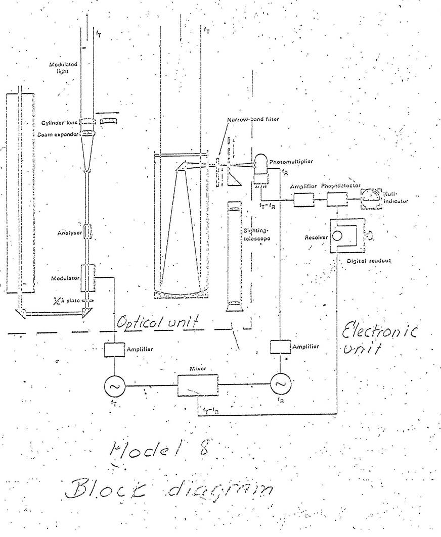
Principle of the modulation
The demodulation system of the Model 8 is different from earlier systems in that the delay time used for setting the phase of the high frequency demodulation signal so that the Null indicator points to 0 (zero), has been replaced by a resolver which has the following functions.
The emitted beam is modulated by one frequency (the received beam has also the same frequency), and the phase i.e. the time moments for the maximum intensity is dependent upon the distance and measured in the following manner. The sensitivity of the photocell varies in phase with another signal which lies 1.5 kHz below the measuring signal. The consequence of this is that the signal in the photocell output has a frequency equal to the difference between the measuring and photocell signals i.e. 1.5 kHz.
The phase shift of this low frequency signal, expressed in degrees, is identical to the phase shift of the measuring signal. To determine the first mentioned, a 1.5 kHz reference signal is formed by direct mixing of measuring and photocell signals. Thereafter, the phase of the reference signals is analysed in the resolver before being sent to the detector unit.
The detector unit is connected on the output side to the Null indicator. The resolver is turned until the Null indicator points to 0. The phase shift of the resolver is proportional to the angle turned. This is read from a three figure register which is adjusted so that the sum of the four readouts included in a measurement on a frequency are equal to an L-measurement in millimetres. By combining the measurements against reflector “R” with the measurements of a known stretch in the Geodimeter “C”, the distance can be calculated as in earlier instruments. Due to the fact that the Model 8 as such a long range that it can be difficult to determine the total number of 2000 metre intervals, a fourth frequency has been implemented which permits a non-ambiguity determination of distances up to 50 km. Thus within the field of application of the Model 8, which under good visibility conditions can exceed this limit, a non-ambiguity measurements are always obtained.
The advantage of the demodulation system used in the Model 8 is that distance measurements can be conducted without calibration tables. Besides, long term stability is also improved. On a practical level this means that the uncertainty of a measurement that is independent of distance, which for earlier instruments was about 10 mm, is reduced to about 5 mm. The meteorological uncertainties have, based upon experience, resulted in an uncertainty of the computed speed of the beam of about 1/1,000,000.
Electronic unit
The main selection of the electronic circuitry of the Model 8 is mounted on a frame located above the optical unit.
The electronic circuitry is constructed of a number of sub-units, each with a fixed function.
The high voltage unit for the laser and photocell
This unit provides voltage for the laser (3 kV at 7 mA) and a stabilised voltage of about 1,500 V for the photomultiplier. It is connected to the 12 V supply. The parts of the unit to conduct the high voltage are embedded in plastic.
The low-voltage units converts 12 V DC to 28 V DC for feeding the electronic circuitry.
The transmitter unit generates the four measuring frequencies and amplifies these to the required level for the modulator.
The reference oscillator generates the reference signals lying 1500 Hz from the measuring signal.
The mixer
The measuring and reference signals are mixed and the unit emits a 1500 Hz low frequency signal which is sent to the resolver.
The amplifier and detector unit
The week output signals from the photomultiplier are amplified to the level required by the detector unit wherein the comparison is made between the phases of the measuring and reference signals.
|
Technical Specifications |
|
|
Range |
Minimum distance about 15 metres out to 60 kilometres in daylight or darkness. The range is depended on visibility and reflector arrangement. |
|
Accuracy |
6 mm +1/1,000,000 x the distance measured |
|
Modulation frequencies |
F1 29970.000 kHz F2 30044.922 kHz F3 31468.500 kHz F4 31465.500 kHz |
|
Receiver frequencies |
F1 29968.500 kHz F2 30043.422 kHz F3 31467.000 kHz F4 31464.000 kHz |
|
Frequency accuracy |
±0.5 x 1/1,000,000 |
|
Crystal oven temperature |
+53°C (cycling negligible) |
|
Effective wavelength |
632.8 nm (0.000 000 6328 m) |
|
Elevation adjustment |
±15° |
|
Approximate dimensions and weights |
|
|
Instrument |
23 kg - 0.30 x 0.56 x 0.25 m |
|
Instrument base |
4.5 kg - 0.17 x 0.11 m |
|
Transport case |
12 kg - 0.55 x 0.95 x 0.50 m |
|
Backpack for unit |
3 kg - 0.36 x 0.37 x 0.8 m |
|
Reflector with one prism |
0.4 kg |
|
Reflector with three prisms |
1.1 kg |
|
Multiholder for three reflectors with 3 prisms each |
0.4 kg |
|
Recommended tripod |
Wild T3, Kern DKM3 or equivalents |
|
Other |
|
|
Power consumption |
Depending on operating conditions of crystal ovens and lamps 6 to 7 Amps at 12 V DC |
|
Power source operation |
11-13 V DC |
|
Temperature range operation |
-25°C to +35°C |
|
Laser |
Spectra Physics type 120 |
|
Power |
5 milliwatts |
|
Divergence |
1.5 milliradian (operated at - 7 mA, 3 kV DC) |
|
Optical data - Receiver |
|
|
Focal length |
0.600 m |
|
Aperture |
0.090 m |
|
Magnification |
42 times |
|
Focal plane aperture |
0.2, 0.3 and 0.5 mm |
|
Corresponding projected area |
0.3, 0.5 and 0.8 metres per kilometre |
|
Optical data - Transmitter |
|
|
Beam width |
0.02 m |
|
Beam divergence |
0.1 metres per kilometre |
AGA GEODIMETER MODEL 8
INSTRUCTIONS FOR OPERATION
Erect the tripod over the point making the tripod head as level as possible.
Attach the tilting head to the tripod and centre it over the point.
Place the Geodimeter on the head and lock the Geodimeter in place with the lever.
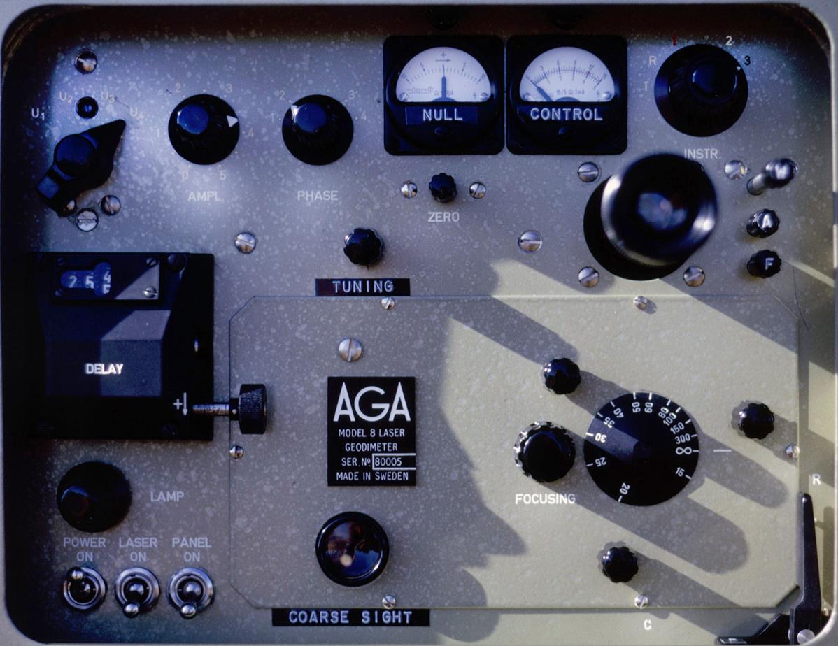
Open the front lid and the rear lid over the instrument panel.
Check that all toggle switches are in the OFF position.
Connect the battery cable to the instrument and the alligator clips to the battery. Note that the red connector is plus and the black is minus.
Set the Instrument knob (INSTR - top right) to position 1 (Volts) and check the battery voltage on the Control Gauge. The voltage should be 11.5 - 12.5. Note: if the control instrument deflects to the left the battery is hooked up with wrong polarity.
Turn switch marked "LASER" to the ON position and turn switch marked "POWER" to the ON position. Frequency knob (top left) should be at U1.
Check battery voltage. (11.5 - 12.5 volts).
Pull out the eye piece and push in the aperture stop marked "A" to its right.
Turn Calibrate lever (bottom right) to "R" position.
Focus the eye piece so that' the reticule is sharp. Swing in the cylinder lens by turning lever from "P" to "R" position.
Point the instrument towards the reflector using the coarse sight.
Observe the reflector area through the eye piece. Focus the instrument on the target area.
Sweep the horizon with the instrument in the approximate target area until a reflection is observed. Note that in certain cases it is easier to find the reflector with a spike filter in using lever marked "F".
Set lever "P” into “C" position.
Observe the reflected light through the eye piece and make fine pointing with the tangent screws. As this pointing is being made the reflector should lie within the reticule. Focus for sharp image of the reflector or reflected light.
Set the instrument switch to position “R”. Check that the instrument reads between 2 and 3 on the lower scale. Note that the instrument will cycle approximately three divisions as the oven thermostat is switching on and off after the initial warm up time.
Set the instrument switch to position "T" and check that the readings are approximately the same as in position "R".
Set the Instrument knob to 2.
Adjust the Tuning knob until the control instrument makes a maximum deflection.
Set the instrument switch to position 3, which is the position in which the instrument switch should be when a measurement is taken.
Check that lever "P" is in "C" position (the cylinder lens is not introduced).
Switch out the eye piece by pulling lever “A” out to desired aperture Stop.
Check that the spike filter is in by pulling lever “W” out.
Fine adjust the pointing by using the control instrument and. the tangent screws. The control instrument should give maximum deflection for proper pointing.
Re-adjust if necessary the mirror on the receiving optics with the three mirror adjustment knobs. For proper adjustment the control instrument should show maximum deflection
Fine adjust the focussing with the focussing knob to obtain maximum deflection on the control instrument. Check the signal strength. The control instrument should read approximately 0.5 – 0.8 on the lower scale indicated by the green area. The signal strength can be adjusted by the grey wedge knob marked "W", by the aperture stop marked "A" and by the amplitude setting. Normal amplitude setting is 2.5. On weak signal or low voltage the amplitude setting may be increased.
Complete measurement as outlined below and record meteorological data.
MEASURING
Reflector measurement U1
Set the frequency switch to position U1.
Set the phase switch to position 1.
Set the counter to zero.
Turn the counter (in plus direction) untill the null indicator indicates zero. The null indicator may not be stable but oscillate around the zero mark.
Record the reading on the counter.
Turn the counter in plus direction and observe the direction in which the null meter is travelling. Record the sign S or + if the null indicator travels in the same direction as the counter; 0 or - if they travel in opposite directions.
Set the phase switch in position 2. Re-adjust the counter to obtain a null reading on the null meter. Record the counter value.
Set the phase switch to position 3.
Turn the counter until a null is obtained. Record the value and observe which way the needle is travelling compared to the Counter and record the sign.
Set the phase switch to position 4.
Turn the counter until a null is obtained. Record the value and observe which way the needle is travelling compared to the Counter and record the sign.
Calibration measurement U1
Set the calibrate lever to C position.
Check that the frequency switch is still in position U1.
Set the phase switch in position 1.
Adjust the grey wedge for the same signal strength as used during the reflex measurement.
Set the counter to zero and repeat same steps as above.
Calibration U2
Set the frequency switch to position U2.
Set the Phase switch to position 1.
Set the instrument switch to position 2.
Tune the instrument for maximum deflection on control instrument.
Set the instrument switch to position 3. Repeat the calibration measurement as for U2.
Reflex measurement U2
Complete measurement as outlined in reflex measurement U1 but with frequency switch in position 2.
Reflex measurement U3
Set frequency switch to position U3.
Set phase switch to position 1.
Set the instrument switch to position 2.
Tune the instrument for maximum deflection on the control instrument.
Set the instrument switch to position 3.
Complete measurement as outlined in reflex measurement U1.
Calibration measurement U3
Complete measurement as outlined in calibration measurement U1. Check that the frequency switch is still in position U3.
Calibration measurement U4
Set frequency switch to position U4.
Set phase switch to position 1.
Set instrument switch to position 2.
Tune instrument for maximum deflection on the control instrument.
Complete measurement as outlined in calibration measurement U1.
Reflex measurement U4
Check that the frequency switch is in position U4
Set the phase switch to position 1.
Complete measurement as outlined in reflex measurement U1.
Measure and record meteorological data.
Measure and record if applicable any eccentricities of the Instrument from the station mark.
Level the instrument with the bubble located on the left hand side of the tilting head. Record eccentricity with proper sign.
Measure the instrument height and record.
|
|||||
|
|||||