DETERMINATION OF MAGNETIC DECLINATION
Introduction
During the past four years the Victoria Branch of the Australian Survey Office has been requested to provide the Magnetic Declination at various sites by direct field observations. These requests have come from the Department of Transport (Air Group) for the purpose of providing Magnetic bearings of runways at aerodromes, and to ascertain the correct magnetic declination at. Radio Navigational Aids. Prior to these specified requests this information was obtained by interpolation from the current "Magnetic Variation Chart" (See Fig. 1) which is compiled by the. Bureau of Mineral Resources, Geology and Geophysics and obtainable from that Department. These charts are compiled from constantly recorded data obtained from various observatories throughout Australia and provide isogons (lines on a map joining points of equal magnetic declination) covering Australia, together with lines denoting the secular variation (the heavier lines on Fig. 1). This data is current at the time of production of the plan, and this date must be included if the declination is to be taken from this chart.
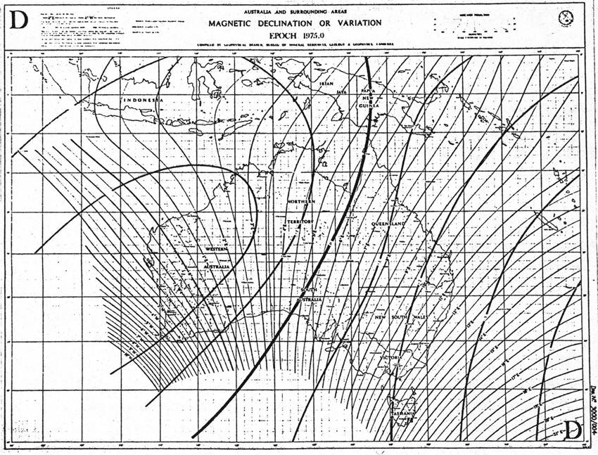
Fig. 1 Magnetic Variation Chart.
More recently, requests have been received from the Defence Department (Air) to provide information on the most suitable area to establish a site for the calibration of aircraft compasses. This request stemmed from difficulties the Royal Australian Air Force were having in obtaining compatible compass readings in the Point Cook area.
Each of the above requests for the determination of magnetic declination has requested an accuracy of 0.1 degrees of arc. This report illustrates the methods by which the 0.1 degree accuracy is readily observable, but also contrasts this accuracy with the influence that will be introduced into the magnetic declination by the time of day and the position on the site that the observations are taken. These variations are usually greater than the specified accuracy.
Equipment
As mentioned in the preceding paragraph, all requests for the determination of magnetic declination have required an accuracy of 0.1 degrees of arc. An investigation was carried out to determine the most suitable instrument to provide this accuracy. This office was already in possession of a Wild Trough Compass mounted on a Wild T1 theodolite, but before proceeding with this instrument, consideration was given to the purchase of a Wild TO Compass theodolite. However it was decided that the TO theodolite would not provide any more accurate answers than the T1 (both read direct to 1 minute), the T1 would probably be more adaptable to everyday survey work, and the Department would not be required to outlay the additional cost of a new theodolite. It should be noted here that the Wild Trough Compass cannot be mounted on a T2 theodolite as these are manufactured from steel while the T1 and T1A are brass.
Method of Observation
Before commencing any observations it is necessary to obtain the difference between the optical line of sight and the pointing of the compass needle i.e. when the compass is pointing towards magnetic north the telescope will probably not be pointing in exactly the same direction due to errors in the mounting of the compass. To obtain this difference it is necessary to read the magnetic bearing of a line of known magnetic bearing. The Bureau of Mineral Resources, Geology and Geophysics constantly monitor a baseline in Canberra and it is [was] possible to arrange to have the theodolite calibrated, or make arrangements to carry out the calibration personally.
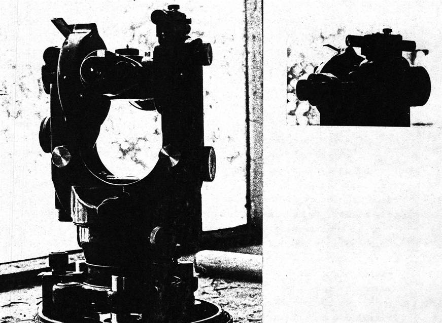
Fig. 2 Wild Trough Compass Mounted to T1 Theodolite.
The method of observing with the Wild T1 and Trough compass is as follows:
· Set 0º 0’ on the top plate of the instrument.
· Depress the button on top of the compass, allowing the compass needle to swing and seek magnetic north.
· Using the lower plate, bring both ends of the compass needle into coincidence.
· The magnetic bearing of the line is observed by unclamping the top plate and reading the bearing to the desired point.
It has been the practice of this Office to take eight readings along the line and the spread would not be expected to exceed three minutes. An inexperienced observer may have some difficulty in attaining this consistency initially due to the difficulty in aligning the ends of the compass needle; however with practice these results will be consistently obtained. It is important that the time of the observation is recorded to enable the calculation of diurnal variation. This will be expanded on later.
Whilst observations are being carried out, care must be taken that no metal objects are carried by the observer, particularly watches, and that the area is clear for a radius of at least 20 metres of metallic objects which may cause a deflection in the compass needle. This will include vehicles, fences, electric motors, electricity wires, underground pipes, two way radios etc.
If the reason for carrying out the observations is to obtain the magnetic declination at the point, some consideration should be given to the method of obtaining true bearings at the site prior to commencing observations. In most cases the sites have been at or near an aerodrome in which case a connection to the Australian Map Grid will have been carried out, so obtaining true bearings will cause no problems.
However if the declination is required at a remote site it will be necessary to carry out either a sun observation for azimuth or a connection to the Australian Map Grid.
Corrections
On completion of the field observations there are various corrections to be applied to the readings prior to the publication of a magnetic declination at the station.
These corrections are :
(a) Instrument Index Error - this has already been discussed under "Method of Observation" and requires no further comment except a reminder that it must be taken into account. To give an example of the magnitude of this correction, the index error on the two instruments in this Office are -0° 8.5' and +3° 30.4'.
(b) Diurnal Variation - An oscillation of the compass needle about its mean position throughout the day. The range of this variation is approximately 10-20 minutes throughout the day, but varies greatly depending on the solar activity or magnetic disturbance at the time. This will be further expanded under “Magnetic Storms".
The Diurnal Variation is automatically recorded on a magnetogram at various monitoring stations throughout Australia and copies of this graph for the day of observation can also be obtained from the Bureau of Mineral Resources. The Diurnal variation is fairly constant over a large area and graphs recorded in Canberra would be quite suitable for the reduction of observations taken anywhere in Victoria.
If an immediate on-site value for the magnetic declination is essential, then diurnal variation could be ignored to a large extent if observations were taken out over a 24 hour period at regular intervals, at any one station. However this is normally impracticable, not only on the basis of costs, but also because the diurnal variation does not fluctuate about the same mean position each day. Hence if 0.1º accuracy is required, it becomes necessary to reduce the diurnal variation to some known quantity.
From the magnetograms for each month the Bureau of Mineral Resources select the five "quietest" days i.e. when the solar activity is least and the diurnal variation has the least fluctuations, and then calculate the magnetic declination on these days. These are meaned to give a monthly mean. This monthly mean can be then used as the datum for the reduction, but it is necessary to wait until about the first or second week of the following month to obtain this figure. Other options are available for the reduction of results and these will be discussed at length later.
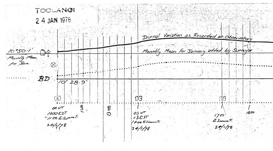
Fig. 3 Typical Magnetogram during "Quiet" Conditions.
Interpolation of Diurnal Variation from the Magnetogram
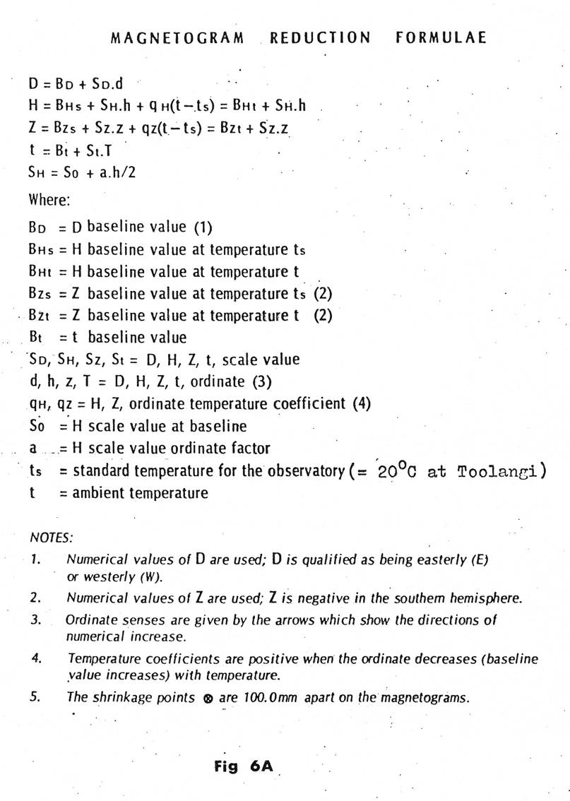
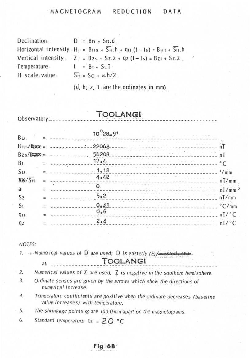
The baseline marked BD represents a fixed declination as determined on the "Magnetogram Reduction Data" as "BD". The heavy line above the baseline, marked D represents the declination at any given time (each dot is at a 5 minute time interval on Universal Time. Add 10 hours to this scale for Eastern Standard Time). The vertical scale to determine the declination above the base line is fixed by each millimetre equaling 1.18 minutes of arc.
To determine the declination, the monthly mean must be plotted onto the graph then the diurnal variation can be calculated at any time around the monthly mean, by multiplying the number of millimetres the heavy line is above or below the monthly mean by 1.18 (the vertical scale). On calculation of the diurnal variation, it is then added to or subtracted from the observed bearing, depending on whether the diurnal variation is above or below the monthly mean. See Figs. 6A and 6B for Bureau of Mineral Resources Magnetogram Reduction Data.
(c) Secular Variation (or Annual Variation) - a constant and gradual change in the magnetic declination at a point over a long period. In Victoria this variation is approximately 2 minutes easterly per annum. However this may increase or decrease and possibly become westerly as time continues. The secular variation is obtained annually by the Bureau of Mineral Resources from the twelve monthly means. These variations do not need to be considered in the reduction of the observations but the secular variation at the site does need to be shown on the plan. As stated in the Introduction, this can be obtained from the "Magnetic Variation Chart".
(d) Irregular Variation - This is caused by magnetic storms. These are magnetic disturbances that are irregular and relatively large variations in the strength and direction of the earth’s magnetic field. They vary in type from those with a sudden commencement where variations of 5° in 15 minutes have been recorded, to those with a gradual commencement which tend to last longer, typically a week to 10 days, and tend to recur at 27 day intervals.
These storm currents are the results of shock waves and clouds of charged particles reaching the earth as a result of:
i. a major solar flare in the case of sudden commencement magnetic storms, or
ii. a stream of particles in the solar wind in the case of gradual commencement magnetic storms.
Magnetic storms vary in intensity over the earth's surface and are larger at high latitudes. Variations exceeding 1º are rare but may be encountered.
No observations should be carried out when these unstable conditions exist, so prior to commencing the survey it is necessary to obtain predictions of impending storms from the Ionospheric Prediction Service.
This service provides a tape recorded answering service of the intensity of any disturbance in the magnetic field. This intensity is given by an open ended international scale commencing at 0 and is known as the "A Index". A number below 20 will indicate stable to fairly unstable conditions, 20-25 will indicate active conditions and above 25 will indicate storm conditions.
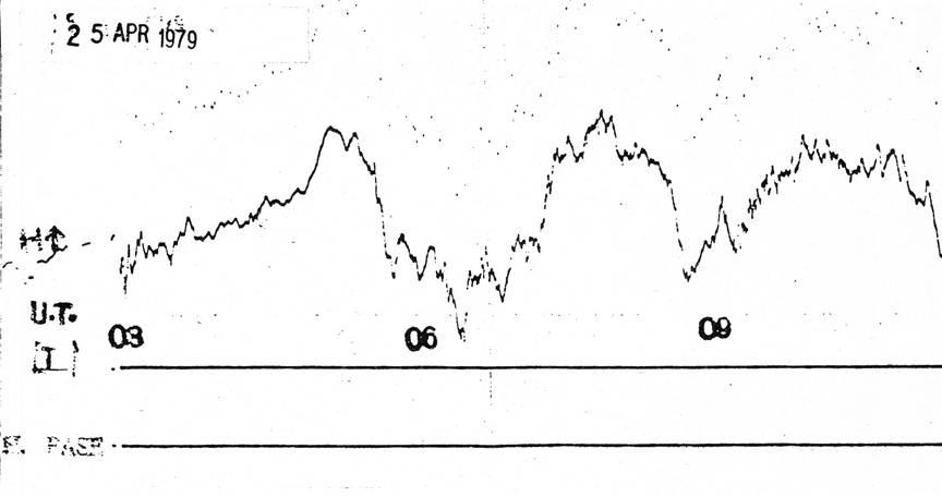
Fig. 4 Example of Magnetogram during a Magnetic Storm.
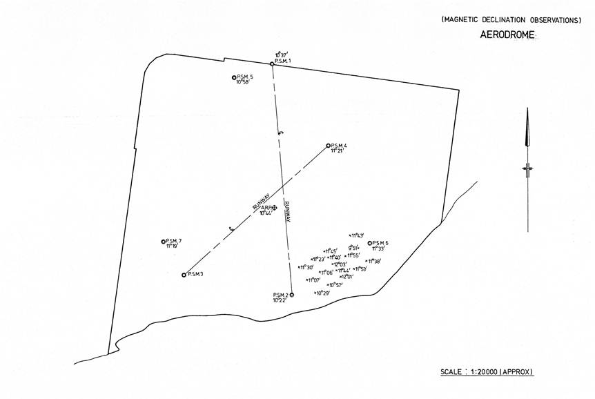
(e) Local Variations - due to local magnetic attractions in the area. This may include rock or mineral deposits under the surface, or man-made objects such as fences, water pipes, electricity wires or buried scraps of metal. One project carried out by the Victoria Branch of this Office gave variations with a range of 2º 20' over an area of 200 metres x 200 metres, including a 1º variation in two stations 30 metres apart. Further investigation revealed the land was reclaimed and had been an old tip site. On another occasion, the observations carried out from a PSM differed by 0º 45' when a piece of water pipe 2 feet x 3/4" which had been used as a marker, was removed. These variations are of a completely unknown quantity and the only way to resolve them is to carry out observations over a large area and to ensure that the area is clear of any visible local attractions.
Results of Surveys
[As this report is old the information in this part of the report has been deleted to avoid the accidental use of specific data – Ed.]
Compass Swings
The purpose of compass swings is to calibrate either the magnetic compass or Gyro compass in an aircraft. It is necessary to carry out this operation on completion of any major repair work on the aircraft. The standard method used to calibrate compasses is to face the aircraft towards magnetic north, set up a landing or datum compass (e.g. Wild B3 Compass, See Fig. 5) about 20 metres from the aircraft on the production of the centreline of the aircraft (obtained by the alignment of the tail and nose wheel in the cross hairs of the compass). The aircraft compass and the landing compass are read and the difference noted. This operation is carried out on the other three cardinal bearings and then adjustments made with a compensator fitted to the aircraft. The entire operation is carried out again, this time at 30° intervals, and if any final adjustments are required they are carried out after this operation.
A compass calibration chart is prepared which gives the corrections to be applied to compass readings to eliminate small errors on various parts of the compass circle.
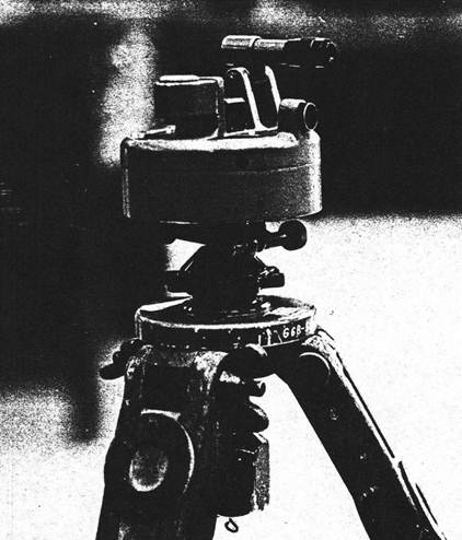
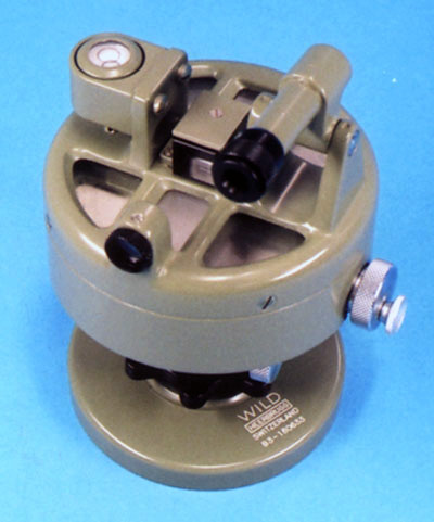
Fig. 5 Wild B3 Compass (Landing or Datum compass)
This method has been widely used to calibrate aircraft compasses for a long period of time and is a simple and generally foolproof method, as both the datum compass and aircraft compass are under the same magnetic influences. The only precaution that should be taken is to obtain a prediction of impending magnetic storms from the Ionospheric Prediction Service prior to the commencement of the calibration. The large fluctuations caused by these storms can result in an inconsistency between successive readings due to the time delay in taking observations while large differences in the magnetic variation are occurring.
The other requirement of course, is that no local variations occur throughout the site, the reason for carrying out the survey to select a suitable site.
There is an electronic method available for calibration of gyro compasses but expensive equipment is required for this operation and according to our investigations only the Air Force have it. Using this method does not require the rotation of the aircraft and consequently is favoured for large aircraft.
Gyro Compasses
The operation of a gyro is based on the principal that when spinning rapidly the horizontal axis on which the gyro rotates takes up a position in the meridian plane (facing true north). In this position the gyro spins in the same way as the earth (from West to East) and as a result there is no interference from gravity so the gyro holds this position. Consequently this principal is used to determine true north.
However the gyro in a gyro compass system is used for another purpose in which use is made of its property to resist torques which tend to alter the alignment of the spin axis.
The main components in the gyro compass are:
(a) The Flux Valve - this is a magnetic azimuth detector which senses the horizontal component of the earth’s magnetic field. The flux valve is normally located in the wing tip or similar stable magnetic location in the aircraft. A compensator is fitted to the flux valve to compensate for local attractions that may be caused by electrical currents or metal in the aircraft. This consists of four magnets which are rotated to cancel any magnetic disturbances.
(b) The Gyro - this is an electrically driven element which is precessed to the magnetic heading reference of the flux valve.
In this system the flux valve senses the direction of the horizontal component of the earth’s magnetic field and converts this information into an electrical signal which is applied to the slaving circuits of the gyro. This slaving amplifier precesses the gyro to give a drift free heading reference, maintained by the gyro to an accuracy of ± 2 degrees. The magnetic heading or longitudinal axis of the aircraft is read relative to this heading reference.
Summary
As a result of the surveys carried out by this Office it is apparent that the equipment is available to readily attain the 0.1 degrees accuracy that is specified in the survey requests. However, once the observations have been carried out to this accuracy the question arises as to the best method of showing these results on a plan. As stated earlier, the first method adopted by this Office was to reduce the observations to the monthly mean as published by the Bureau of Mineral Resources. This method is quite satisfactory in that it enables the results to be reduced to a known figure. However, if the monthly mean happens to be erroneous due to prolonged solar activity, in relation to the preceding and following months, this error will be projected into the survey result. The delay in obtaining these results also causes some concern, particularly if the project is completed early in the month, and the resultant delay of one month in publishing final plans to the client often cannot be tolerated.
This delay resulted in an alternative method of publishing the results as observed with corrections applied for index error only, and the actual time and date of observation recorded on the plan. Again this method is not completely satisfactory because it places the onus on the client to determine the diurnal variation and reduce the result to a satisfactory datum.
Possibly the most satisfactory, is to obtain the monthly mean for the preceeding 12 months and extrapolate the next monthly mean from these results.
Consideration must be given to the local differences, often well outside the specified tolerance of 0.1 degrees, that are obtained over an area such as an aerodrome. To take observations at one station may well give a result that would not be consistent with the mean of observations taken at various stations throughout the area. Consequently to obtain the magnetic declination at a site it has been found necessary to take a series of observations at various stations over the site and mean these observations for a final result.
In addition to variations within an aerodrome are the results of surveys taken along the approaches to aerodromes. These show variations of over 1º in the extent of a runway approach (15,000 metres). It could be expected that future surveys will produce larger variations than the 1.2 degrees variation found in the extent of an approach to this date. The unknown factor on the subject of approaches and any magnetic bearings taken in relation to aircraft, is what variations could be expected above the earth’s surface where there are no local attractions at all, and of course this is where the aircraft are taking their compass readings.
Another result of these surveys is that although substantial local variations have been found, the mean of these variations has not differed greatly from the declination interpolated from the "Magnetic Variation Chart".
Compass Swings - The method used to calibrate compasses is quite valid and generally foolproof as both compasses are under the same local magnetic anomalies and providing consideration is given to large discrepancies in irregular variations and local variations, no problems should be encountered.
Conclusion
Although the observations and reductions can be carried out to readily obtain the requested accuracy of 0.1 degrees of arc at a point, consideration must be given to the reason for the survey and whether a satisfactory result may be obtained by interpolation of the results from the "Magnetic Variation Chart", the cheapest and quickest method.
If interpolation from the chart is not suitable because of the purpose of the survey and it is considered necessary to carry out field observations, then the accuracy of the observed declination is meaningless without regard to local variations, diurnal variations and irregular variations, the position of the observation together with the datum to which these observations are reduced. If substantial differences are found with the value interpolated from the "Magnetic Variation Chart", then this must also be considered with the reason for the survey, this is, the use made of the magnetic declination.
This report has been written to assist other officers in making a decision on the best method of obtaining the results required, the most suitable method of presentation, together with some insight into the pitfalls that may be encountered in the observation of magnetic bearings.
Senior Technical Officer Grade 1
(estimated date mid-1980s)