OPTIONS FOR MORE EFFECTIVE
NAVIGATION AND POSITION FIXING
Limiting the Alternatives
The solutions to position fixing are many and varied and it will aid this discussion if some limits to the field are defined at the outset. As cost of equipment is a parameter of immediate significance to all it will be used here to set the boundaries for discussion.
It appears to the writers that the navigation/position fixing system (or systems) that is likely to gain universal acceptance amongst a diversity of users will involve equipment that is within the cost spectrum defined by manual methods (compass, sextants, speed logs etc.) at one end and inertial or sonar Doppler systems at the other. The former although requiring only small capital outlay in equipment are costly in operation. They are labour intensive, time consuming and in any case of limited accuracy. At present the latter carry a capital cost which would be outside the budgets of all, but a few users.
Criteria for Evaluation of Systems
Many factors come into consideration in assessing a system of position
fixing:
coverage in space (range)
coverage in time (availability)
precision of location
cost
ease of operations
The first four of these are rather obvious points of contention, the other has been included as it would seem that to all users (in this particular environment) except perhaps those involved directly in hydrography and bathymetry that position fixing is an adjunct to the main task, not an end in itself, and so should not dominate the operation.
In more general terms the surveyor must consider:
the position accuracy required
the area in which the study is to be carried out (distance from shore, approximate depth of water, size of vessel likely to be used, etc.)
dynamic and/or post-mission positioning requirements
availability of shore control
interfacing requirements with other instrumentation (e.g. echo-sounder, side scan sonar, sub-bottom profiler, gravimeters, magnetometers, etc)
position methods (e.g. geometry, quantities to be measured)
duration of surveying operation and periods during which positioning is required (e.g. 24 hrs/day, all weather)
the availability of necessary measurement instrumentation
the availability of necessary computational devices to compute positions (and plot them) and/or accuracy estimates
cost, both capital and running
With these factors in mind, the ideal system would be one which covers the whole area of operations at all times, gives location to an accuracy that will satisfy the most exacting user, be largely automatic in operation and be of little (well reasonable) cost.
Precision of Location
It is not intended in this paper to become too involved with the technicalities of the various position fixing systems, but rather discuss their performances in the light of the criteria listed in Section 2. However, there is a need to establish some basic technical background that should allow the comparison of systems to be more pertinent. The first of these concerns the concepts of precision and accuracy. A distinction is often drawn between these two terms in that a "precise" instrument is one that will repeat measurements with very little variation while an "accurate" instrument gives a measurement that is close to the true quantity. At times in position fixing precision is all that is needed - i.e. the instrument will give a similar measurement of a quantity at any Time it is repeated. However, when locations are to be re-established at different times by different equipment it is obvious the instrument needs to be both precise and accurate thus establishing precise absolute position.
In this paper the term standard deviation will be used to refer to the reliability of location of various systems and for simplicity the comparison will be made by quoting the standard deviation of location in absolute terms (i.e. to bring both precision and accuracy into account) for one direction only. For example, in these systems where location is achieved by measurement of two distances to established stations the reliability will be defined by the standard deviation of one of the measurements. If this standard deviation is say 10 m, this means in raw terms we would expect for that measurement that :
for 68% of the time the error is less than 10 m
for 95% of the time the error is less than 20 m
and for 99% of the time the error is less than 25 m
For this example it does not mean the location will be to that absolute precision in all directions - the geometry of the situation will play a part.
Figure 1 shows the magnitude and direction of minimum and maximum standard deviation of location for a two range system with standard deviation of 3 m. This diagram will go some way in explaining the discrepancy between the manufacture and the user's figure.
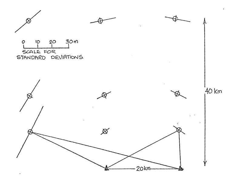
Figure
1. Maximum and minimum standard deviations of location for Range-Range system.
Standard deviation for single range 3 m.
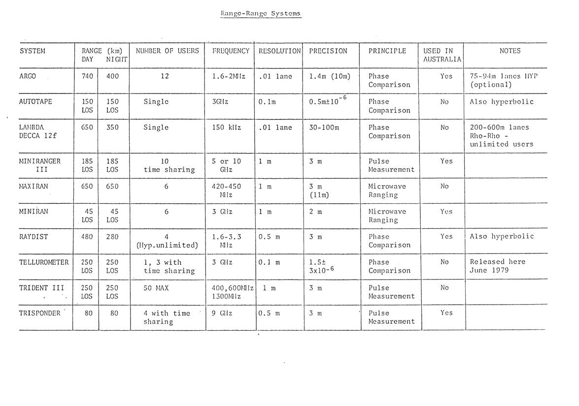
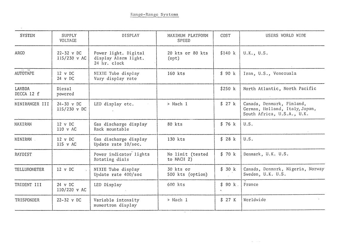
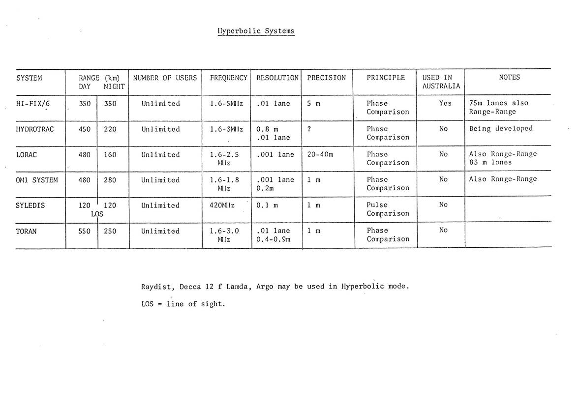
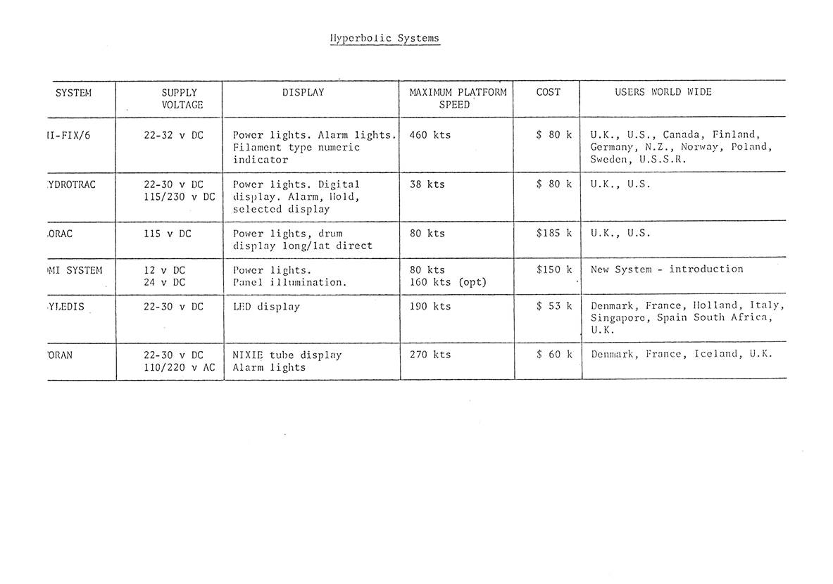
Range-Range and Hyperbolic Systems
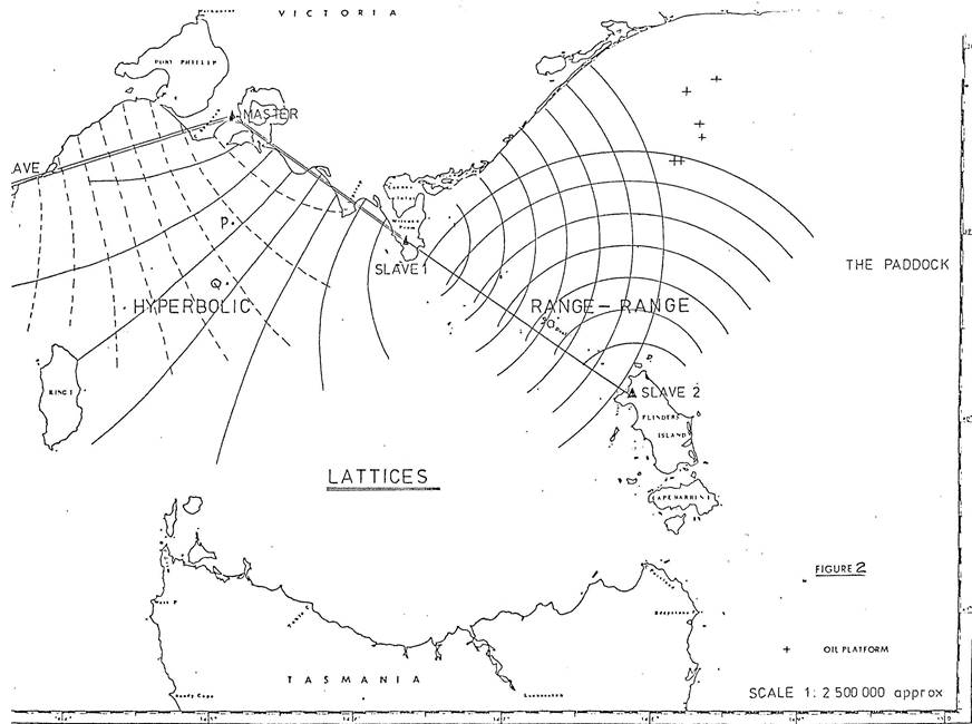
The underlying theory of position fixing of a number of systems involves the use of electromagnetic waves to measure ranges from ship to known shore locations. In the "range-range" systems, two distances to shore stations are directly measured. In "hyperbolic" systems the difference between two ranges is measured. In this case, 3 shore stations are involved so that two differences can be measured. In most cases the height of the instrumentation above sea level and earth curvature is ignored. Thus the geometry is reduced to two dimensions and a simple plane solution for position is applied. For the "range-range" (alternatively "rho-rho" or "two-range") system the solution merely involves the intersection of two circles centred on the shore stations and having radii equal to the measured ranges. This is shown in Figure 2. The precision of location is closely related to the angle of intersection of the circles, the closer the angle being to 90° the more precise the fix. The precision does not deteriorate to any marked degree over the longer ranges.
The short range systems give unambiguous solutions as the full distance is measured. Other systems only record the displacement within the lanes and lane count must be kept to give the full range.
The normal configuration for the range-range system is that a "master" unit is installed on the ship which interrogates the "slave" units on shore. By the nature of things the master unit is the more expensive. The slave units can, in some systems, be shared by a number of master units but that number is strictly limited.
The hyperbolic systems although more complex in theory achieve some economics in practice even though three shore stations, a master and two slaves, are involved. This is because the ship only needs a receiver to detect a phase difference in the electromagnetic waves and any number of users can share the one set of shore stations. It is intrinsically a multi-user system. Positions of constant phase difference for ranges from any set of master and slave units lie on a hyperbola. A family of these curves can be established and forms a "lattice" on which the ship's position can be tracked. As before the angle of Intersection of the two sets of hyperbolae govern the precision of location. The "lane" width of the lattice is not constant as can be seen in Figure 2. The precision will deteriorate with lane width which occurs with increase in distance from the shore stations. The solution for position with hyperbolic systems is always ambiguous. The curves in Figure 2 could represent those of zero phase difference and would mean the measurements made at P would be identical with those at Q. Thus with all lane counting systems if the count is lost, which can happen for a number of reasons, the ship is lost also. Alternative navigation procedures or movement to a known position is needed to re-establish the lane count.
The Effect of Electromagnetic Wave Propagation
The systems described in section 4 achieve the measurements by determining the time taken for electromagnetic wave to travel between master and slave station. The velocity of the wave in the atmosphere and the path it takes between units will affect the accuracy and performance of the instruments if they vary from those allowed for in instrument’s design.
Short range systems using waves with frequencies in the region of 5000 MHz are designed to use the "direct wave", the medium range systems with frequencies around 2 MHz are designed to use the "ground wave". The presence of "reflected waves" or "sky waves" as shown in Figure 3 and 4 may cause errors due to longer path length and/or cause the signal to be blanked out.
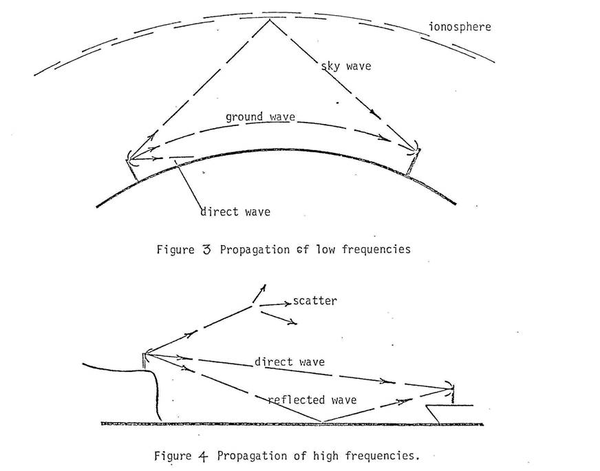
Long range systems using frequencies of 100 kHz and below rely on the ionosphere and the earth's surface to provide a wave guide for propagation. Obviously, the height of the ionosphere will affect the path length taken by the wave and consequently the diurnal change in height of the ionosphere will cause errors.
The systems often rely on the velocity of the wave being constant. It will, however, change with atmospheric conditions and surface conductivity. For instance, medium wave instruments if calibrated to measure accurately over sea water will not do so well over land. This can cause significant errors if the proportions of land and sea along the path is not known. Some Operational Problems with Range-Range and Hyperbolic Systems
Short Range Equipment
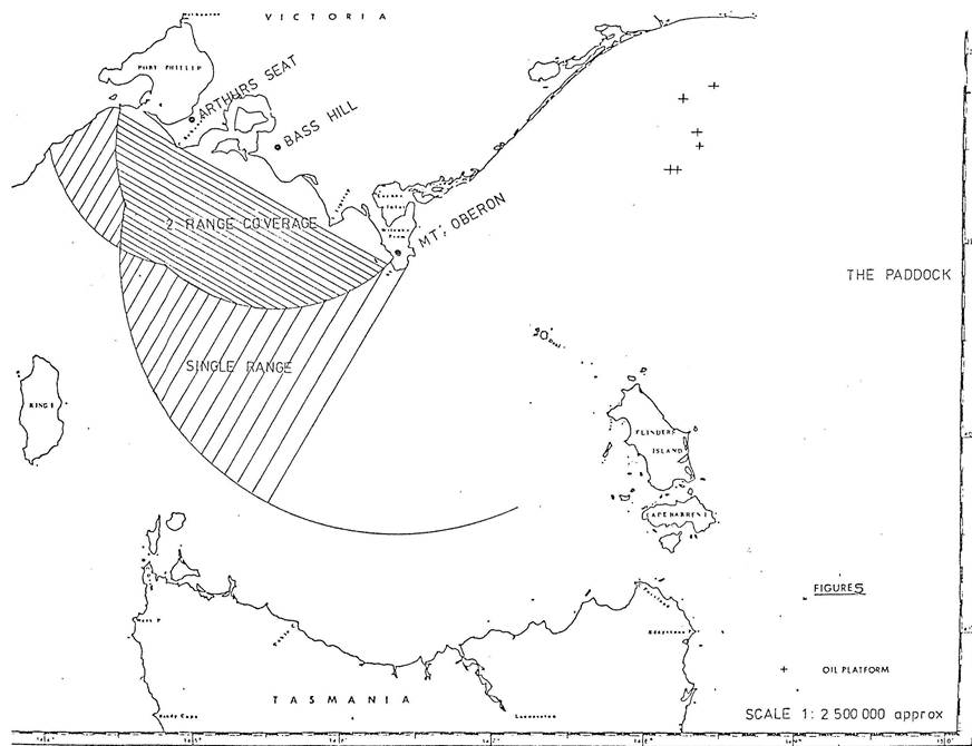
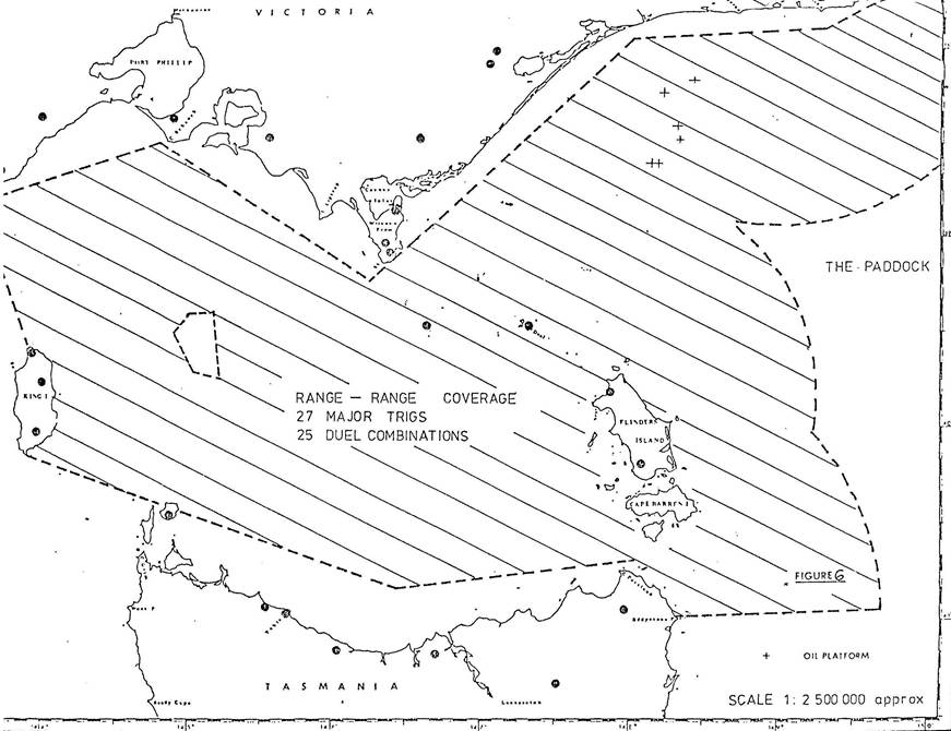
The fact that this equipment needs line of sight (LOS) between units and that sector antennae are often used with the slave stations means the coverage is in practice greatly reduced. For example, a study of Bass Strait showed that with the deployment of 5 slave stations on the most elevated positions in an area allowed a coverage of less than 1/3 of the Strait (see Fig. 5). The situation further involved the need to re-direct the antennae in some cases and this in itself added significantly to the logistic problem (see Fig. 6). The problems of multipath effects of loss of accuracy and signal fading are ones which seem to be tolerated or avoided by varying the mode of operation.
Medium Range Equipment
To quote from a Report from U.S. Department of Commerce (Sweden 1977). The more significant problems which face the 2 MHz medium range systems are:
Systematic Errors as a Function of Position Due to Varying Propagation Velocity.
Because the 2 MHz electromagnetic signal propagation velocity depends upon the surface electrical conductivity, transmission over water and over land, or even different types of land, occurs at different effective phase velocities. Knowing the appropriate velocity to use, or the phase correction to make as a function of .range, is thus a potential problem, particularly within coastal regions. It should not be a major problem if all stations are located on the shore and positioning is being performed at sea with only sea water in the transmission path.
Sky Wave and Storm Interference
At the extreme ranges of their operation, the medium range systems can be affected by sky wave interference with the more predictable ground wave. Particularly if this is a problem for nighttime operation. With ranges restricted such problems should not be significant. Almost all systems, however, experience high noise and signal dropouts during electrical storms.
Ambiguities
Perhaps the most serious problem in operation of the medium range systems is due to the fact that most systems are inherently ambiguous, and must be zero set and continuously monitored for "lane" jumps or loss of signal which results in the loss of lane count.
Frequency Allocation
The frequency band in which the medium range systems operate is frequently very crowded, resulting in problems in obtaining frequency allocation. In many cases, system designs are strongly influenced by the need to minimize the frequency bandwidths utilized.
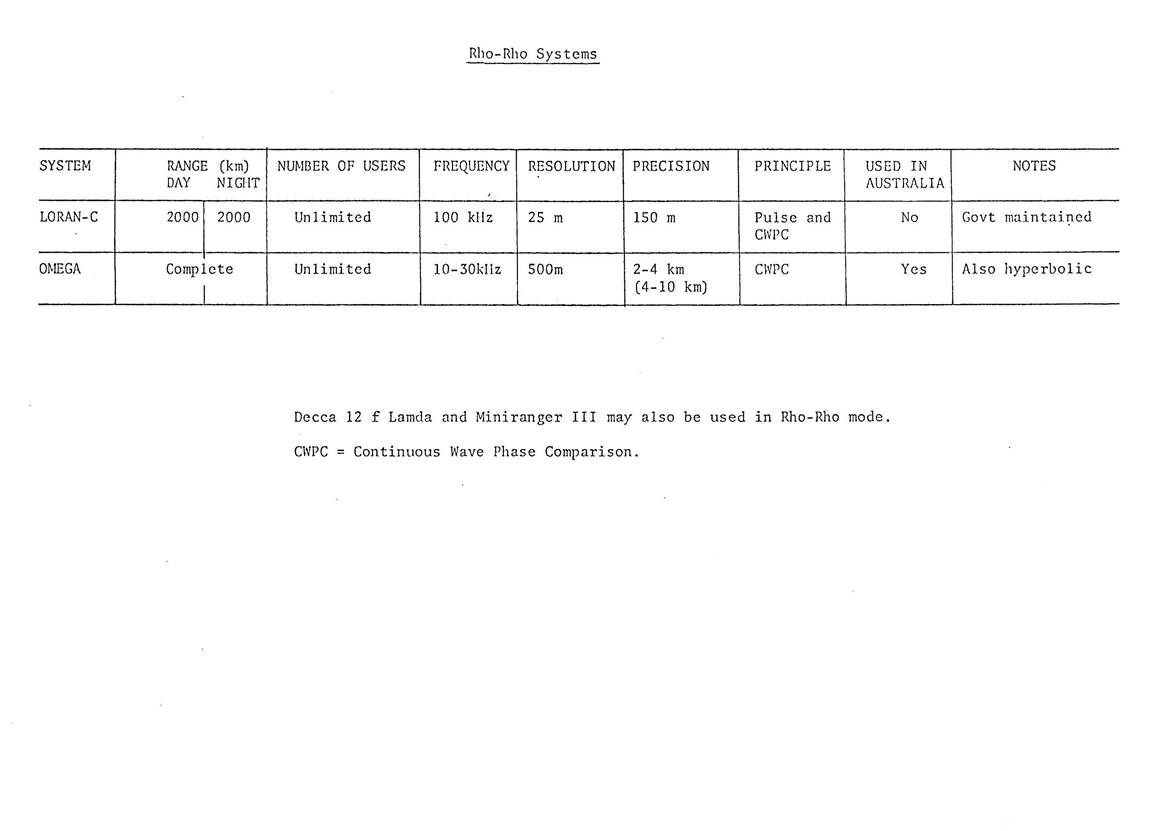
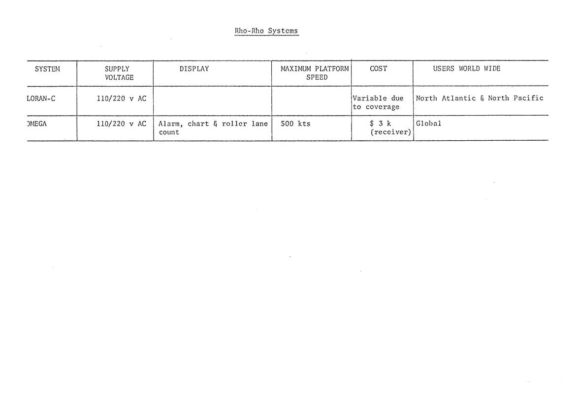
Long Range Equipment
To quote from a paper by Maepna (1978) : The stated accuracy goal of the Omega system is 1 nmi root mean square (rms) error probability during day conditions and 2 nmi rms at night (Eaton et al. 1976). This rms value can be translated to a day and night 95% circular error probability of 3.8 nmi; in other words, 95% of all errors should be less than 3.8 nmi.
The realized Omega navigation accuracy, however, is often much less than this goal. To illustrate, the accuracy of the Omega system was assessed by the Western Pacific Omega Validation study during 1976 and 1977. The 95% circular error value over the entire Western Pacific area was estimated to be between 6.3 and 7.3 nmi. The basic intent of this study was to determine the corrections to the PPCs which will be required in order to bring the actual Omega accuracy in line with the system goal. However, this process is slow. The corrections for the last area to be validated, the South Pacific, will not be available for general use until one or two years after the completion of the South Pacific monitor program, currently scheduled in 1982 (Eaton et al. 1976).
The factors affecting realized Omega navigation accuracy are extremely complex, and include the following :
Predicted Propagation Correction (PPC) accuracy
Diurnal transition effects
Geographic propagation anomalies
Solar related propagation anomalies
Omega signal availability
Tradeoff of navigation response versus smoothness
Use of Omega charts and PPC tables in manual receivers
Satellite Navigation
A system of navigation or position fixing that differs completely from those discussed previously is the satellite navigator. In simple terms it is a combination of radio receiver and computer that determines position from the known orbit of a satellite and the Doppler shift in a signal (continuously broadcast on two frequencies) as the satellite passes overhead. The orbital parameters are encoded into the signal and the operation is remarkably automatic once the first few passes are detected. Time taken for pass and computation is about 15 minutes.
Its advantages are that it is independent of shore stations, multi-user, all weather and with predictable precision. Manufacturers claim a standard deviation of fixation of around 100 m for a single frequency receiver and 37 m for the more sophisticated two channel systems.
Its main disadvantage is that the average time between acceptable passes is 60 to 70 minutes in these latitudes and the period between passes can be as long as 6 hours. For continuous fixation other methods must be used. Also in a dynamic situation the velocity vector must be supplied to the computer and the solution is particularly sensitive to errors in this information - for instance, 0.2 nautical mile per knot of speed error.
Hybrid Systems
The development of hybrid systems by users is an indication that to many there is no one ideal system. Each of the systems can have weaknesses in range, availability, precision or cost when considered from any particular user's point of view. The fact that weaknesses in one system can be complemented by strengths in another allow for a great deal of improvement in performance if the systems are run as a combination. (Maepna 1978) and (Eaton et al. 1976) give details of some of the more successful hybrid system Satellite navigation combined with Loran C, Doppler Sonar or Omega; Loran C with Decca 12 etc.
A recent development that can illustrate the power of a hybrid system is that of satellite navigation with Omega. As seen above the major disadvantage of satellite navigation on its own is the length periods between satellite passes. Omega's greatest drawback for many users is its accuracy in the absolute sense. However, Omega can give much improved precision if used in the "differential" mode, that is to track movement over shorter periods. The combination of the two using satellite navigation to give absolute position as each satellite passes and Omega to track movement between passes (and supply an accurate velocity vector) is a most promising one. Maepna gives results of a static test of the system where some 1500 tests were done over an 11 day period and quotes a standard deviation of near 0.4 nmi. Sea trials still in progress suggest this figure could be close to the mark for normal operations.
If any conclusion can be drawn from this paper it is probably that for most users a hybrid system developed from the newer electronic aids or perhaps between the new aids and traditional methods will prove to be the most beneficial.