Aerial Survey Camera Calibration Facility at Natmap
Background
Towards the end of the 1950s the number of aerial survey cameras in Australia started to increase. To ensure that the metric quality of any aerial photography acquired by these cameras would be suitable for mapping, the National Mapping Council required such cameras to undergo regular calibration checks. Nevertheless, it was standard practice for Natmap to demand a contractor supply a recent camera calibration certificate before any camera was used to acquire mapping photography for National Mapping under contract. Given that all such aerial survey cameras were manufactured overseas, this meant these cameras could be out of service for significant periods while they were sent back to the manufacturer for calibration checks.
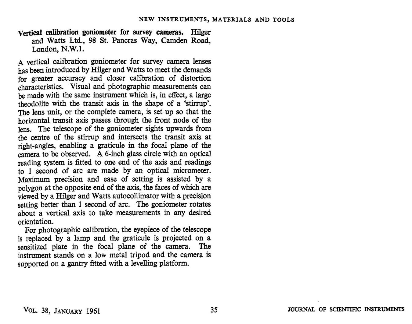
To minimise the impact of this obligation on Natmap’s contractors, in the early 1960s National Mapping purchased a Hilger and Watts Vertical Goniometer. Hilger and Watts Limited described their instrument in their 1961 article, Vertical Calibration Goniometer for Survey Cameras. Refer Annexure A. A goniometer is an instrument that either measures an angle or allows an object to be rotated to a precise angular position. The term goniometry is derived from two Greek words, gonia, meaning angle, and metron, meaning measure. Goniometers are widely used in surveying, navigation, communications, crystallography, medicine and physical therapy. However, in most cases the goniometer has been specifically designed for the task and has a more common name. The sextant and earlier astrolabe are goniometers used in navigation; likewise, the theodolite is a goniometer used in surveying.
The Hilger and Watts Vertical Goniometer was installed at the Commonwealth Scientific and Industrial Research Organisation’s (CSIRO), National Measurement Laboratory (NML) in Sydney. The goniometer’s operations were described by Patterson in his 1978 paper, Calibration of Photogrammetric Cameras. As early as 1929, the options and procedures for the calibration of aerial survey cameras had been explicitly documented in the book Calibration of Surveying Cameras by Captain Martin Hotine, then a Research Officer of the Air Survey Committee of the United Kingdom.
In 1982, changes to CSIRO’s charter saw the responsibility for camera calibration transferred to National Mapping and the Hilger and Watts Vertical Goniometer installed at the Dandenong office. Following the move and installation of the equipment, the new facility was then registered with the National Association of Testing Authorities (NATA) in the field of Metrology.
|
|
|
|
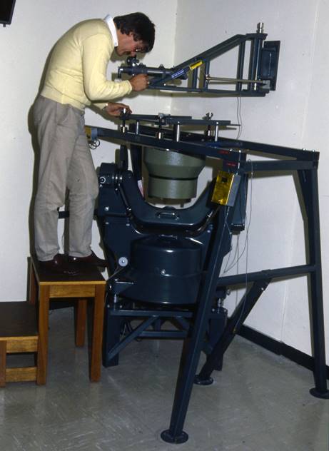
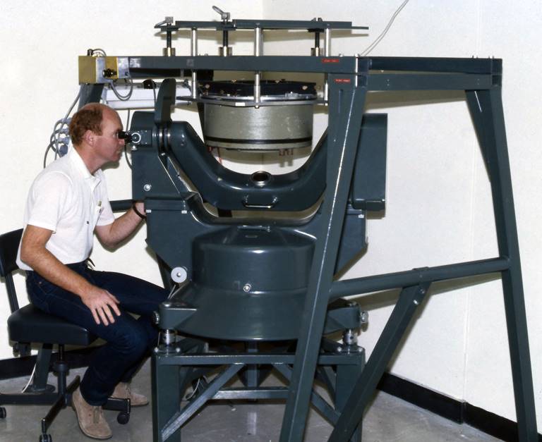
Figure 1 : Hilger and Watts Vertical Goniometer at Natmap. Left photograph shows the autocollimator being used on a Wild wide-angle (152mm or 6inch nominal focal length) lens cone. The right photograph shows angular observation in progress on a Wild super wide-angle (89mm or 3.5inch nominal focal length) lens cone. Note that although of different lengths, each camera lens cone is held at the same distance from the goniometer by the mounting plate. |
|
Natmap’s facility
The goniometer was similar to a large theodolite having a telescope supported on two trunnions that permitted rotation about a horizontal and vertical axis. The major difference was that the goniometer only provided the ability to read angles on the vertical circle, whereas a theodolite allowed both vertical and horizontal angle readings. These vertical circle readings were to the nearest second of arc.
Over the goniometer was a separate large steel frame in which the camera was mounted. This frame allowed the camera to be aligned both horizontally and vertically.
An autocollimator was attached to the wall allowing it to be swung out of the way when not required. The autocollimator was used for accurate camera alignment. Refer Figure 2 for more detail about the goniometer’s components.
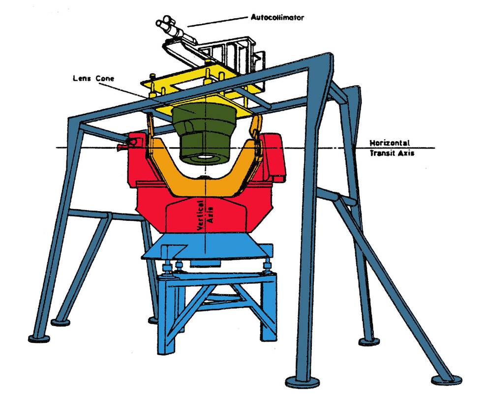
Figure 2 : Hilger and Watts Vertical Goniometer with colour-coded components. Red indicates the main unit which revolved around the vertical axis and allowed reading of the angle at which the orange ‘stirrup’ was set. The blue indicates the base of the goniometer which was raised off the floor on a triangular mount and levelled by three screws. The grey rack, which was independently set over the goniometer, held the green camera or lens cone using a suitable yellow mounting arrangement to hold the camera at the right distance from the goniometer. Above and separately mounted was the autocollimator unit.
A manually operated overhead winch was installed to enable the heavy but delicate and expensive cameras to be lifted safely and lowered into the holding rack. Various electronic power supplies and cables developed by CSIRO and Natmap personnel were available as the camera’s shutter had to be held open during the calibration process. As it was crucial to let the camera settle in the goniometer and acclimatise, on arrival, a camera would be fixed into the rack and left overnight before any calibration activity was undertaken.
For clarity, early aerial cameras had the lens cone integrated with the camera body as in the Wild RC9. Later aerial cameras like the Wild RC10 had a camera body for which there were interchangeable lens cones. For calibration, the RC9 body and lens were necessarily mounted in the goniometer whereas only the requisite RC10 lens cone needed to be mounted. In this paper the word camera refers to both cameras and lens cones.
A suitable calibration plate was set on the camera’s focal plane. This plane contained engraved fiducial marks which were used to centre the plate. These plates also contained precisely engraved markings spaced every 1 millimetre across each diagonal. Through the goniometer’s telescope the operator could see these marks and read the vertical angle subtended by any specific mark. A sequential, predetermined series, 20 to 30 approximately, of equally spaced marks across both diagonals were observed by the operator, who recorded the vertical angle at each required mark. A set of such observations then became the input data to determine the camera’s calibration parameters. While the light ray from an object usually travelled through the camera lens to the focal plane to be imaged on the film, the goniometer reversed the process. In the goniometer, the light ray travelled from the plate on the focal plane through the camera lens to be viewed by the operator as it emerged. This approach of reversing the direction of travel of the light ray made no difference as the optical geometry of the lens fixed the light ray’s behaviour. Only changes to the optics themselves or their mechanical environment could influence the light ray’s behaviour. The goniometer did have a photographic calibration facility, but as pointed out by Bell and Mayer (1956) the visual calibration methodology contained less uncertainty than the photographic, and was therefore preferred. Purists could and did argue that camera calibration should be done in the operational environment of the aircraft and not a laboratory. While Natmap was developing this technique however, the goniometer was the only cost-effective alternative.
National Mapping used its in-house computer to process the angular calibration data and produce the necessary hard-copy calibration documentation for the camera’s owner. The 1984 paper, Aerial Camera Calibration Facilities in Australia by David Henderson and John Manning, described and contained an indicative calibration parameter document.
A valuable asset was camera calibration files for all the cameras CSIRO had calibrated over the years. This historical archive allowed any significant change in calibration parameters to be identified and checked and reported to the camera owner. Such a significant change in a camera’s parameters might have required the camera be returned to the manufacturer for adjustment.
By the late 1980s, new generation cameras were being manufactured to a precision that exceeded the goniometer’s capability and the goniometer was sold along with other ex-Natmap assets like its aircraft. Nevertheless, for some 30 years the Hilger and Watts Vertical Goniometer was used to ensure the metric quality of the aerial photography acquired in Australia.
Compiled by Paul Wise, October-December 2015.
Sources
Bell, GA and Mayer, I. (1956), The Calibration of Aerial Survey Cameras, Cartography, Vol.1, pp.144-147.
Clarke, TA and Fryer, JF. (1998), The Development of Camera Calibration Methods and Models, Photogrammetric Record, Vol.16, No.91, pp.51-66, accessed at : http://www.vision.caltech.edu/bouguetj/calib_doc/papers/DevelopmentCameraCalibrationMethodsModels.pdf
Henderson, David and Manning, John (1984), Aerial Camera Calibration Facilities in Australia, Proceedings International Society of Photogrammetry and Remote Sensing, XXV Congress, Commission 1, pp.114-119.
Hilger and Watts Ltd. (1961), Vertical Calibration Goniometer for Survey Cameras, Journal of Scientific Instruments, No.38, pp.35.
Hotine, Martin (1929), Calibration of Surveying Cameras, Professional Papers of the Air Survey Committee - No. 5, H.M. Stationery Office, London, Chapters 1 and 4.
Optical Metrology Centre (undated), Camera Calibration Methods, Handbook of practical camera calibration methods and models, Ch.4, pp.4-1 to 4-15 accessed at : http://robots.stanford.edu/cs223b04/JeanYvesCalib/papers/clarke_book/Handbook%20Chapter%204.pdf
Patterson, JB. (1978), Calibration of Photogrammetric Cameras, Photogrammetria, No.34, pp.69-78.
Annexure A